Principles of Attachment Selection for Implant Supported Overdentures
| Principles of Attachment Selection for Implant Supported Overdentures | Hamid Shafie, DDS* and George Obeid, DDS** |
|
**due to the size of some of the pdf files some might be hard to load, download the pdf instead. |
|
| triangle of the female abutment. (Fig. 4B) The abutment driver is initially used to insert the female abutment with finger pressure. The opposite end of the abutment driver then accepts a .05” hex tip for a torque wrench. (Fig. 4C) Insertion tips are also available for Bio-Torq® and Dyna-Torq® wrenches and for latch-type torque controllers that interface directly with the female abutment. (Fig. 4D)
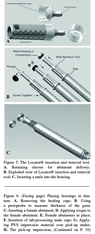
The abutment retention sleeve is used to secure the female abutment during insertion. The sleeve is placed over the end of the abutment driver and the Locator® female is then placed through the sleeve. (Fig. 5A) To remove processing or worn nylon males, the male removal tool (Fig. 5B) is slightly unscrewed from the middle section of the male removal tool. The inverted conical tip is inserted into the worn male and pulled straight back for removal. The male removal tool is then screwed completely into the middle section to protrude the plunger and kick off the male insert. A new nylon male is placed on the middle male seating section and inserted into the metal housing. (Fig.5C)
Using the Laboratory Indirect Technique The following steps are used in the laboratory indirect technique with the Locator® overdenture attachment. • Remove healing caps. (Fig. 6A) • Measure the tissue depth (deepest point) from the mating surface of the implant to the crest of tissue. (Fig. |
 |
|||
|
SROMS |
|
8 |
|
Volume 19.6 |
